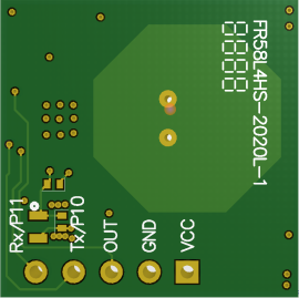
FR58L4HS-2020L

FR58L4HS-2020L

FR58L4HS-2020L is a high-performance 5.8G radar sensor FMCW ranging and presence sensing launched by Ferry Smart Intelligent. The radar module uses the Doppler principle to transmit high-frequency electromagnetic waves through the antenna and receive the initial reflected waves to judge the movement of objects within the coverage area and give corresponding electrical signals. Signal. Module size 20*20MM The chip integrates 5.8G microwave circuit, intermediate frequency amplifier circuit and signal processor, with high integration and good production consistency. The module has a built-in 32-bit MCU and a transceiver antenna, which greatly improves the sensing performance of the sensor.

The radar module has a long sensing distance, a wide angle, no dead zone, and the lens and lens aging problems are not affected by temperature, humidity, airflow, dust, noise, brightness and darkness. Widely used in smart lighting, smart door locks, smart security, smart home appliances and other fields.

Hardware Instructions

2.png

Device distribution diagram on the front and back of the module

FR58L4HS-2020L hardware reserves 5pin connection pin header, the pin distance is 2.54mm

The following is a detailed description of each PIN corner name, function, working range, etc.

Pin pin

Functional remarks

remarks

TXD

Burning port tdio

Compatible with UART TX and IO ports

RXD

Burning port TCLK

Compatible with UART RX and IO ports

OUT

output signal

The output signal is high and low level (0V / 5V)

GND

Grounding pin

VCC

Power supply module

LDO is not attached by default, and the power supply voltage is (4.5 ~ 5.5V). If 12V power supply is required, LDO needs to be added, and the power supply VCC is 5V ~ 12V

Technical Parameter

parameter

Small value

Typical value

Large value

Company

remarks

Emission frequency

5725

5800

5875

MHz


input voltage

4.5

5

5.5

V

If 12V power supply is required, LDO shall be added

Output high level


5


V


Output low level


0


V


Working current


33


mA


Sensing distance

0.1

/

70

M

The distance can be adjusted according to demand

Delay Time


2


S

Specific requirements are adjustable

Photosensitive threshold


N/A


Optional, no photosensitive paste by default

Antenna beam angle


100


°


size


20*20


mm


working temperature

-30


85


Storage temperature

-50


125


Description of packaging method

The module is packaged in a blister box and placed in the blister box;

1. Put the blister boxes into the carton according to the stack of 10 boxes;

2. The air raid in the carton is filled with instant noodles to reduce transportation wear;

3. Bubble film is placed on the bottom of the carton to prevent transportation wear;

4. Cover the top layer with bubble wrap and seal with tape to prevent shaking.

3.png

Installation Precautions

1. When installing the antenna, there should be no metal shells or components on the front of the antenna to avoid shielding the signal. Blocks such as plastic or glass are allowed, but the block should not be close to the front of the antenna;

2. Try to avoid directing the radar antenna to large metal equipment or pipes, etc.;

3. When installing multiple radar modules, try to ensure that the antennas of each radar module are parallel to each other, avoid direct irradiation between the antennas, and maintain a distance of more than 1m between modules;

4. The radar sensor should avoid facing the AC drive power supply, and try to stay away from the rectifier bridge of the drive power supply to prevent the power frequency from interfering with the radar signal;

5. It is recommended that the power supply driving capability of the radar module is not less than 50mA, otherwise it may cause the sensor to work

6. When installing, ensure that the installation position of the sensor is firm and stable. The shaking of the radar itself will have a great impact on signal processing.

7. When installing, make sure that there is no object movement or vibration on the back of the radar. Since the radar radio frequency wave is penetrating, the signal on the back of the antenna will also pass through the radar board. If there is an object moving on the back, it will also be collected by the antenna, which will affect the judgment effect. A radome or backplane can be used to reduce the effects of objects behind the radar.

8. When installing, try to ensure that the radar antenna is facing the area to be detected, and the surrounding area of the antenna is open and unobstructed.